The diode symbol is very important in electronic circuits and diagrams. In these diagrams, the diode symbol has a triangle that points to a straight line. The triangle shows the anode, which is the positive end. The line shows the cathode, which is the negative end. This design shows which way the current flows. The current goes from the anode to the cathode. This helps show how the diode controls the current in a circuit. Knowing this symbol helps people working with circuits understand how diodes work. It also helps them see how diodes keep the current going the right way.
Key Takeaways
-
The diode symbol has a triangle and a line. It shows current moves from anode (positive) to cathode (negative).
-
The way you place a diode is important. If you put it backward, it stops current. This can hurt the circuit or the diode.
-
There are many diode types with their own symbols. These symbols show what each diode does. For example, Zener controls voltage. LED gives off light.
-
Always look at the diode symbol and its markings before you connect it. This helps you avoid mistakes and keeps your circuit safe.
-
You can use a multimeter in diode mode to test a diode. It checks if the diode works by measuring voltage drop the right way.
Diode Symbol Basics
Triangle and Line Meaning
The diode symbol has a triangle that points to a line. This is not just a random shape. The triangle stands for the anode, which is the positive side. The line stands for the cathode, which is the negative side. This makes it easy to see how the diode works in a circuit.
The triangle and line also match the parts inside the diode. The anode side is the p-type semiconductor. It has holes that carry the charge. The cathode side is the n-type semiconductor. It has electrons that carry the charge. Where these two meet is called the pn junction. The triangle shows the p-type side, and the line shows the n-type side.
The diode symbol was made in the early 1900s. Engineers wanted a simple way to show which way current should go in circuits. The triangle points the way current should flow. The line blocks the way, just like a real diode does. Sometimes, the letter "K" marks the cathode so people do not get confused.
Current Flow Direction
The arrow in the diode symbol is not just for looks. It shows which way the current should go. In electronics, current goes from positive to negative. So, current moves from the anode (triangle) to the cathode (line). This is how most books and engineers draw circuits.
It is important to know this direction. The diode only lets current pass if the anode has more voltage than the cathode. If you put the diode in backward, it will block the current. That is why the way the diode symbol faces in a diagram is important.
-
The way the diode symbol faces in a diagram tells you:
-
Which way current can go through the diode.
-
If the diode is forward biased (ready to let current through) or reverse biased (blocking current).
-
How the diode will act in the circuit, like in rectifiers or voltage protection.
-
Where to put the diode on a real board, since the cathode often has a stripe that matches the line in the symbol.
-
If you put the diode in the wrong way, it can cause problems. The circuit might not work, or the diode could break. On circuit boards, the cathode is marked with a stripe. This helps you match the symbol to the real part.
Tip: Always check which way the diode symbol faces in the diagram and on the board before you solder or test. This easy step can stop many mistakes.
How a Diode Works
One-Way Current
A diode lets current go in only one direction. This happens because it is made from two special materials called p-type and n-type. When these two materials join, they make something called a PN junction. The PN junction creates a barrier named the depletion region. This barrier decides how current moves through the diode.
When the anode has more voltage than the cathode, the diode is forward biased. In this case, the depletion region gets smaller. Charge carriers can move across the junction. Current flows easily from the anode to the cathode. The diode only lets current go this way. If someone tries to send current the other way, the diode stops it. The depletion region gets bigger, and almost no current moves. This makes the diode helpful for controlling current direction in circuits.
The diode symbol shows this one-way action. The triangle points where current can go, from anode to cathode. The line marks the end where current cannot pass.
The real diode works just like its symbol in many ways: - The triangle in the symbol stands for the anode, and the line shows the cathode. - Current moves in the direction the triangle points, but not the other way. - The diode acts like a one-way door for current, just like the symbol shows. - When forward biased, the diode lets current through, like a closed switch. - When reverse biased, the diode blocks current, like an open switch. - The symbol helps people quickly see how the diode will work in a circuit.
A normal silicon diode needs about 0.6 to 0.7 volts to start working in the forward direction. Germanium diodes need less, about 0.2 to 0.3 volts. If the voltage is lower than this, almost no current flows. When the voltage is high enough, the diode turns on and lets current pass.
Polarity and Orientation
Polarity means which way the voltage goes across the diode. The anode must be more positive than the cathode for the diode to work. This is called forward bias. If the voltage is switched, with the cathode more positive, the diode is in reverse bias. In this state, the diode blocks almost all current. Only a tiny bit of current might flow until the voltage gets very high. If the reverse voltage gets too high, the diode can break and let current go the wrong way. This is bad and can hurt the diode.
How you place the diode in a circuit is very important. The symbol helps people put the diode in the right way. The arrow in the symbol shows the correct way for current to flow. The line in the symbol matches the stripe on the real diode, which marks the cathode. This makes it easy to match the diagram to the real part.
Many circuits use diodes to stop reverse voltage or to change AC to DC. For example, a rectifier uses diodes to turn alternating current into direct current. The symbol helps engineers and students see how the diodes control current in these circuits.
Tip: Always look at the symbol and the marks on the diode before you connect it to a circuit. This easy step can stop damage and help the circuit work right.
The table below shows how the diode acts in different cases:
| Bias Type | Anode Voltage | Cathode Voltage | Diode State | Current Flow |
|---|---|---|---|---|
| Forward Bias | Higher | Lower | Conducting | Yes (Anode → Cathode) |
| Reverse Bias | Lower | Higher | Not Conducting | No |
People use diodes in many ways, like in rectifiers, voltage protection, and signal control. Knowing how a diode works and how the symbol matches what it does helps everyone use diodes the right way in any circuit.
Types of Diode Symbols
Zener Diode Symbol
The Zener diode is special because it controls voltage in a unique way. Its symbol looks like a regular diode, but the bar has bent ends. This shape shows the Zener diode can work in reverse bias after a certain voltage. When forward biased, it works like a normal diode. In reverse bias, it does not let current pass until the voltage reaches the Zener breakdown voltage. At that point, the diode lets current flow and keeps the voltage steady. The bent bar in the symbol helps people see this voltage control feature quickly.
The Zener diode symbol tells engineers this part can handle reverse breakdown safely, so it is good for stopping voltage spikes.
Schottky Diode Symbol
The Schottky diode has a different symbol to show it switches fast and has a low voltage drop. The symbol has an "S"-shaped bend on the bar, making it easy to spot. Schottky diodes use metal and semiconductor materials. This gives them a lower forward voltage drop than normal diodes. They are used in power supplies and rectifier circuits where speed and saving energy are important.
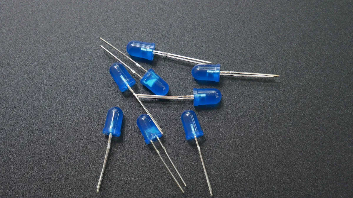
LED Symbol
Light-emitting diodes, or LEDs, have a symbol that shows what they do. The symbol looks like a regular diode, but two arrows point away from it. These arrows mean the device gives off light when current goes through.
-
The arrows in the LED symbol show it makes light.
-
The symbol reminds people to connect the LED the right way.
-
LEDs need current to go from anode to cathode to work.
-
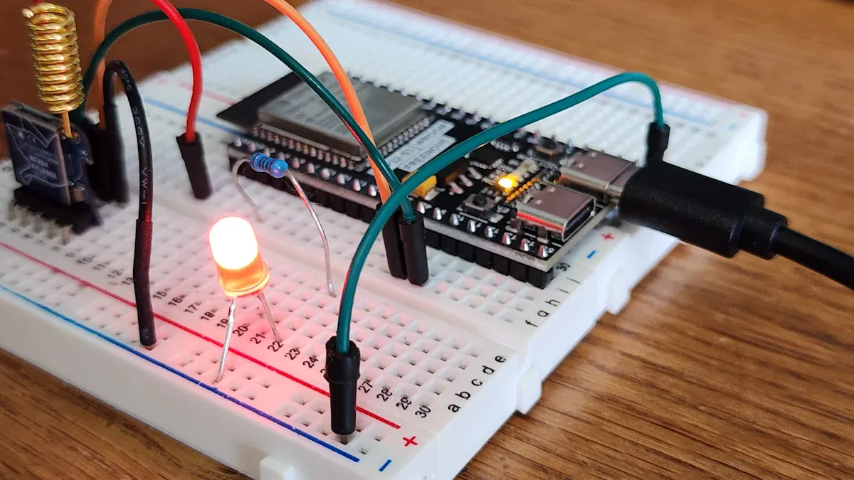
The symbol also shows you need a resistor to protect the LED.
Knowing the LED symbol helps people use LEDs safely and get the right amount of light.
Other Diode Types
There are many other diodes with their own symbols. Photodiodes have a symbol like a regular diode, but arrows point toward it to show they sense light. Varactor diodes add a small capacitor symbol to show they change capacitance with voltage. Each symbol change helps people know what the diode does in a circuit. For example, tunnel diodes and laser diodes use extra curves or arrows to show their special jobs. These symbols help engineers choose the right diode for things like signal control, voltage control, or light sensing.
Using Diode Symbols in Circuits
Identifying Anode and Cathode
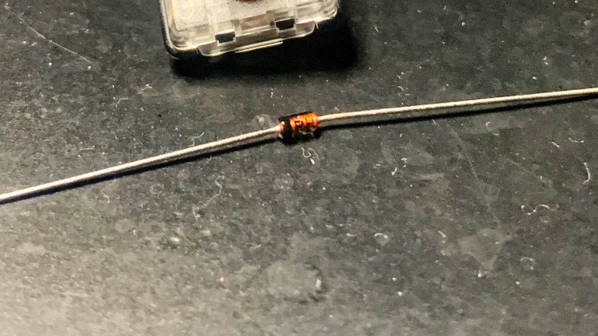
It is very important to know the anode and cathode. The diode symbol has a triangle that points to a line. The triangle is the anode. The line is the cathode. Real diodes have a colored band or ring on the cathode side. For LEDs, the longer leg is the anode. The shorter leg or flat side is the cathode. These marks help people connect diodes the right way.
| Method | Identification Detail |
|---|---|
| Diode Symbol | Arrow shows the anode (positive); bar shows the cathode (negative). |
| Physical Diode Marking | Cathode has a big colored band or ring on the body. |
| LED Leg Identification | Longer leg is anode (positive); shorter leg or flat side is cathode (negative). |
| Multimeter Testing (Diode Mode) | Red probe on anode and black probe on cathode lets current flow; switching them blocks current. |
Tip: Always check which side is anode and cathode before putting parts in a circuit. This stops mistakes and keeps the circuit safe.
Reading Schematics
To read schematics, you must know each symbol. The diode symbol is a triangle next to a line. The flat side of the triangle is the anode. The line is the cathode. Some special diodes have extra lines or bends in their symbols. LEDs have arrows pointing out to show they make light. Photodiodes have arrows pointing in to show they sense light. Knowing these symbols helps you see what each diode does. Reading the symbol right helps you build and fix circuits.
Testing with a Multimeter
A digital multimeter can test if a diode works. The multimeter has a diode mode with a diode symbol. Turn the dial to this mode. Put the black lead on the cathode and the red lead on the anode. A good silicon diode shows about 0.6 to 0.7 volts. Germanium diodes show about 0.3 volts. If you switch the leads, the screen shows "OL" or a high number. This means no current goes through. This test checks the diode’s direction and if it is good.
| Test Condition | Typical Multimeter Reading | Explanation |
|---|---|---|
| Forward Bias (Silicon Diode) | About 0.6 to 0.7 volts | The meter sends a small current, and the diode lets it pass. |
| Forward Bias (Germanium Diode) | Around 0.3 volts | Germanium diodes need less voltage to work. |
| Reverse Bias | "OL" or very high resistance | The diode stops current in this way. |
Note: Using a multimeter helps find broken diodes. Make sure you know which side is anode and cathode for the test to work.
Knowing the diode symbol helps people design and fix circuits with confidence.
-
The arrow in the symbol shows which way current moves. This makes it simple to see how the diode works, like a check valve in pipes.
-
This knowledge helps you put the diode in the right spot, use it safely, and solve problems fast.
If you know the symbol, you can connect and test diodes the right way. Charts, practice with diagrams, and computer tools help you learn faster. Rules in the industry make sure every symbol means the same thing in all diagrams.
FAQ
What does the diode symbol show in circuit diagrams?
The diode symbol in circuit diagrams shows the direction current can flow. The triangle points to the line, which marks the path from the anode to the cathode. This helps people understand how a diode works in electronic circuits.
How do you connect a diode in a circuit?
To connect a diode, match the triangle (anode) to the positive side and the line (cathode) to the negative side. This setup lets current flow the right way and helps protect the circuit from voltage spikes.
What is a rectifier diode used for?
A rectifier diode is used for converting from AC to DC. It allows current to pass in only one direction. This makes it important in power supplies and other electronic circuits.
What are the types of diodes and their uses?
There are many types of diodes, such as Zener, Schottky, and light-emitting diodes. Each type has a special symbol. People use them for voltage control, fast switching, and making light.
How can someone test diodes in a circuit?
Testing diodes with a multimeter helps check if they work. Place the red probe on the anode and the black probe on the cathode. A good diode shows a small voltage drop. This method helps with testing diodes in electronic circuits.
Written by Jack Elliott from AIChipLink.
AIChipLink, one of the fastest-growing global independent electronic components distributors in the world, offers millions of products from thousands of manufacturers, and many of our in-stock parts is available to ship same day.
We mainly source and distribute integrated circuit (IC) products of brands such as Broadcom, Microchip, Texas Instruments, Infineon, NXP, Analog Devices, Qualcomm, Intel, etc., which are widely used in communication & network, telecom, industrial control, new energy and automotive electronics.
Empowered by AI, Linked to the Future. Get started on AIChipLink.com and submit your RFQ online today!


.png&w=256&q=75)


